Ultrasound Data Transferring Between Mobile Devices

Founder & CEO at Azoft
Reading time:
Ever since smartphones became mainstream, we’ve seen many new technologies emerging that make data exchange possible between mobile devices. Near Field Communication (NFC) has gained wide attention in recent years, but only a small percentage of mobile users have adopted it.
One of the recent projects of Azoft R&D team along with our technology partner WUL4 was to develop a technology that would allow phones to exchange info via inaudible sound waves (i.e. ultrasound data transfer), serving as NFC alternative. The main advantage of such a solution is that it’s compatible with all mobile operating systems and doesn’t require any changes to the existing hardware, such as built-in NFC chips.
This solution may be particularly interesting to banks and other companies specializing in money transfers, mobile payments, etc. Inaudible sound waves can be used not only for exchange of data between two phones but also between other devices, for instance, a mobile phone and a payment terminal.
The objective
To create a mobile application that delivers near-field device-to-device communication by leveraging the existing hardware to encode the messages in acoustic waves in the ultrasonic range. The project is still a work in progress and is currently developed only for iOS.
Practical relevance and application
1. Alternative to NFC
NFC technology has been around for several years now but still hasn’t received wide recognition nor did it get into large-volume production. Mobile industry leaders still can’t agree on a single universal format for the protocol of near field communication. Moreover, while manufacturers of Android smartphones support this technology, Apple has been steadily ignoring it.
The current situation of almost no progress in the NFC direction calls for a way out. The main advantage of the ultrasound data transfer approach is that it works with almost every phone. It only requires a speaker, a microphone, and a relatively modern processor, powerful enough to perform all necessary calculations. Virtually all smartphones sold today would be compatible with this technology. NFC technology, on the other hand, requires a special chip to be included in the hardware.
2. Communication between devices running different OS
Again, since data transferring between devices does not require any extra equipment and is implemented on the software level, this technology can be used to exchange info between phones with different operating systems, e.g. iOS, Android, BlackBerry, Windows Phone, etc. This is particularly relevant today, during a time of increasing mobile platform differentiation and growing demand for cross-platform communication.
3. Gesture recognition
The ultrasound technology could be applied not only for data transferring but for gesture recognition as well. For Android, there are already app prototypes that recognize user’s gestures through a camera. The same idea could be realized using ultrasound.
Project overview
Choosing the carrier frequency
The human ear can hear sounds in the range of approximately 20 Hz to 20 kHz. Any frequencies above and below this range are imperceptible to the ear. Consumer audio equipment including speakers, microphones, and amplifiers is designed to work in this frequency range. However, most people have slightly decreased upper hearing limit – about 16 kHz. Very few people can hear any frequencies higher than that.
Mobile devices can theoretically record and reproduce sounds with a peak frequency as high as 22050 Hz. This limit is caused by the maximum possible output sample rate of those devices, which is equal to 44100 Hz.
The usable range is actually a bit lower than that. The frequency response of the phone mic and speaker has a noticeable roll-off above 19 kHz. That’s why we’re going to use frequencies in the range between 16.5-17 kHz to 18.5-19 kHz that can be cleanly reproduced and captured by most devices.
Implementation
So, we have a frequency range in which devices can transmit and receive inaudible sounds or the range for the carrier frequency. Now we need to choose a modulation technique, a scheme that defines how the carrier signal is controlled by a modulating signal. The choice of modulation technique affects the implementation complexity of the modulator and demodulator and error-rate performance at a given speed.
Problem: sound reflections
Sound radiates in all directions and reflects from various surfaces. This results in having reflected waves recorded alongside the direct sound. The sound coming directly from the source to the receiver.
As sound radiates, the wave energy is redistributed in space and an interference pattern is formed which is not necessarily constant in time. The redistribution pattern depends on wave frequencies as well.
Sound reflections cause several issues that we have to resolve. For example, it may happen that the receiver (a microphone) is located at some place where the direct and reflected wave cancels each other out due to the phase shift of the reflected wave. In this case, the amplitude of the received signal may even drop below the noise level. This effect is called a deep fade.
Suppose, we’d like to use frequency modulation for this project and the frequency of the carrier is modulated by a digital binary signal, where 0 and 1 correspond to 17 kHz and 18 kHz respectively. Our results have shown that sometimes a 18 kHz wave can have a relatively low amplitude at the receiving point and at the same point an echo from another 17 kHz wave is recorded with a higher amplitude. This echo wave comes from a 0 that was transmitted before the 1. So, we already have two possible difficulties to take into account.
On the other hand, reflected waves have at least one advantage. In case the receiver isn’t positioned in direct line-of-sight with the transmitter (the microphone and the speaker are pointed towards opposite directions), only reflected waves will be captured by the microphone.
Solution
There are several ways to work around the deep fade effect. We chose the approach of extending the spectrum implemented by transmitting the signal at several frequencies. For example, we can use a frequency sweep from 18.1 kHz to 18.5 kHz to transmit 0’s and a sweep from 17.1 kHz to 17.5 kHz to transmit 1’s.
This approach is based on the premise that deep fade won’t happen for every frequency in a certain range and thus we should extract at least some of the frequencies of the range to correctly decode the signal.
Unfortunately, this solution is not completely immune to decoding errors, so we have to add error-correcting coding to our implementation to avoid them.
Implementing the demodulator
Originally our demodulator was based on Fast Fourier Transform (FFT). FFT outputs the full frequency spectrum of the signal, which is good, but we have to make sure that the number of FFT bins matches the number of harmonics, i.e. to decompose the signal into 1024 harmonics we need 1024 FFT bins.
It turned out that we couldn’t analyze the signal in our frequency range at a satisfactory transmission rate though. Goertzel algorithm was not used, as it produced the same results, although with a performance increase since it analyses selectable harmonics and not the whole spectrum.
The next demodulator that we tried was heterodyne. It works as follows:
- The signal is passed through a high-pass filter that suppresses unnecessary frequencies below 16.5 kHz (we used a 6th-order FIR filter).
- The resulting signal is independently multiplied by 2 sine waves shifted by /2, each having a certain frequency 0. By using a trigonometric identity we get a sum of 2 waves with frequencies -0 и +0, where is the frequency of the received signal. For 0we chose a value of 17850 Hz.
- The result is passed through a low-pass filter, producing a pure wave with frequency-0. Again we used an FIR filter, but this time it was a 30th order filter.
- The amplitude and the modulating frequency are extracted from the 2 quadrature components of the resulting signal. Amplitude is the sum of squares of the quadrature components. Phase is the arctangent of their ratio.
Unlike FFT, the heterodyne demodulator is designed to work with a single carrier frequency at a time, because it cannot analyze the whole spectrum.
The modulating frequency, extracted from the signal using the heterodyne demodulator is pictured below (the transmission consisted of 10101010):
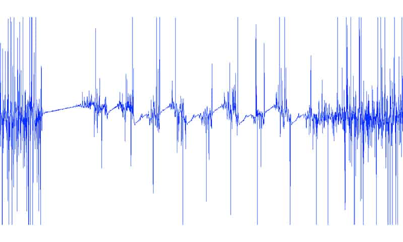
There is some noise in the beginning and at the end of the depicted sample. The beginning of the data frame is marked by a starting symbol (represented by a long linear ramp) that is used to synchronize the transmitter and the receiver. The short pauses between repeated ramps representing 0’s and 1’s are called guard intervals. They’re used to reduce symbol interval interference.
The receiver is able to work in 2 modes:
1. The signal is checked for the presence of a starting symbol. The symbol is detected by counting the number of successive hits of signal values into a moving window, which is big enough to tolerate a small amount of noise:
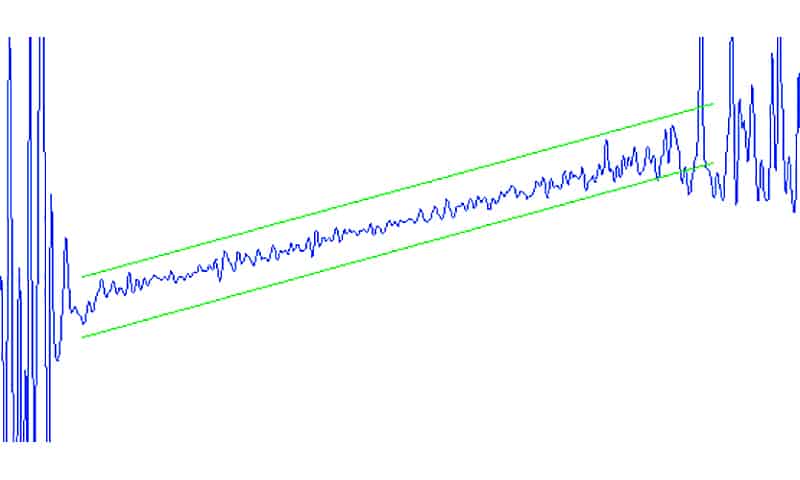
This step is performed for every received sample, i.e. we scan every sample with the moving window, counting hits. If the number of hits reaches a certain threshold, we assume that the starting symbol is detected and find a position within the sample where the number of hits is the highest.
The end of the starting symbol is the point with the highest number of hits. Since we already know the length of 0’s and 1’s and the pauses in between, we can reliably predict their positions in the signal.
2. Every sample is compared to the waveform corresponding to 0 or 1. The comparison is done by the same moving window method as above. The method can be improved by weighting the number of hits with the current amplitude of the signal.
The signal shown in the first picture has a relatively high signal-to-noise ratio. Sadly, this is not always the case. It may happen that the waveform will look like this one:
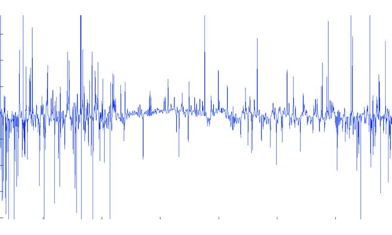
As the distance between the receiver and the transmitter increases, the signal quality gets worse. Both the speaker and the microphone are sort of directional, so their orientation in space also affects the signal quality. The best signal-to-noise ratio is achieved when the speaker is directed straight to the microphone of the receiving device.
The problem of extracting usable components from ultrasonic audio signals with a low signal-to-noise ratio still remains open.


Comments